I’m always looking for things to add to my show that aren’t just more “bullets in coro”. While they do have bullets in coro, the Boscoyo P5 MegaChromaStone also has a P5 panel, which can be used for matrix effects at 64×32, which is enough to be interesting compared to tombstones with bullet matrixes. So, I grabbed a few, along with the corresponding panel kits from Wired Watts.
The tombstone kits I received did not come with instructions, or if they did, I did not locate them. You probably don’t need any manual, as the build is straightforward. It’ll likely take you half an hour to build a P5 tomb, but if you spend 5 minutes skimming my notes, it’ll probably only take you 35 minutes in total.
Build Options
There are several options for the panel part of the build. You can use a variety of panels and controllers, but I’ve opted for the Chameleon Panel Panther Dumb Receiver for mine. This is a slick, relatively inexpensive little board that takes pixel data from a controller long range differential port and uses it to drive the panel. While the Panther can drive some additional pixels (such as the tomb outline), I’ve opted not to use this feature. (My reasoning, since you asked, is that I always fly by the seat of my pants, and I always have pixel ports nearby, so just plugging the pixels into a controller port would be the easiest thing to field-adjust or fix without opening the tomb. I also mostly use 12V pixels, and the power supply in the tomb is 5V. So, no sense making the build more complicated, just to not really use the pixel capability in the field.)
Overall, this will be the simplest configuration to build… just plug in AC power, plug in differential long range data from any controller (if using the HinksPix controllers see my post about the pinout), plug in the outline pixel string, and ready to run.
Parts Needed
The Chameleon Panel Panther Outdoor P5 kit is reasonably complete, including the panel, housing, gasket, power supply, cord+gland, data cable, DC power cabling, controller card, mounting plate, and assorted screws.


In addition to the kit and aforementioned tombstone coro from Boscoyo, the build will also need:
- A string of 100 of your favorite (or, after what happened last year, least unfavorite) 12mm bullet nodes
- Small zip ties to hold the panel kit on the tomb, 4″ work well, black will blend in best
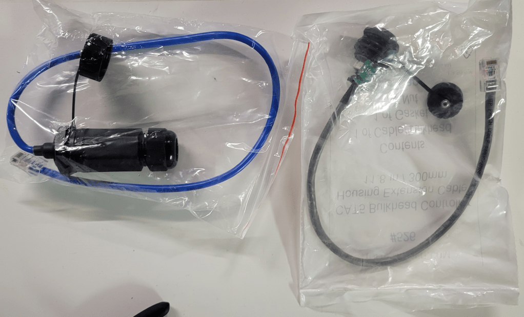
- An RJ45 bulkhead for connecting the long range cable to the tomb; I would recommend either the Network Pass-Through Gland from Wired Watts (blue below), or the CAT5 Bulkhead from HolidayCoro (grey below). The former is a bit bulkier and watertight, the latter a bit cheaper and lighter but should face downward when outdoors. (They’re both fine choices that have served me well over the years. I am using the latter for this build, because I have a few spares here already.)
Assembling the P5 Kit
Cords
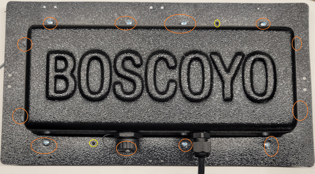
First, drill appropriate holes in the plastic housing. For this build, there is one needed for the data jack and one needed for the PG-9 gland for the power cord. (The larger hole pictured is for the jack, the smaller hole for the power cord.) Fit the bulkhead and power gland, and run the power cord through the gland.


PSU
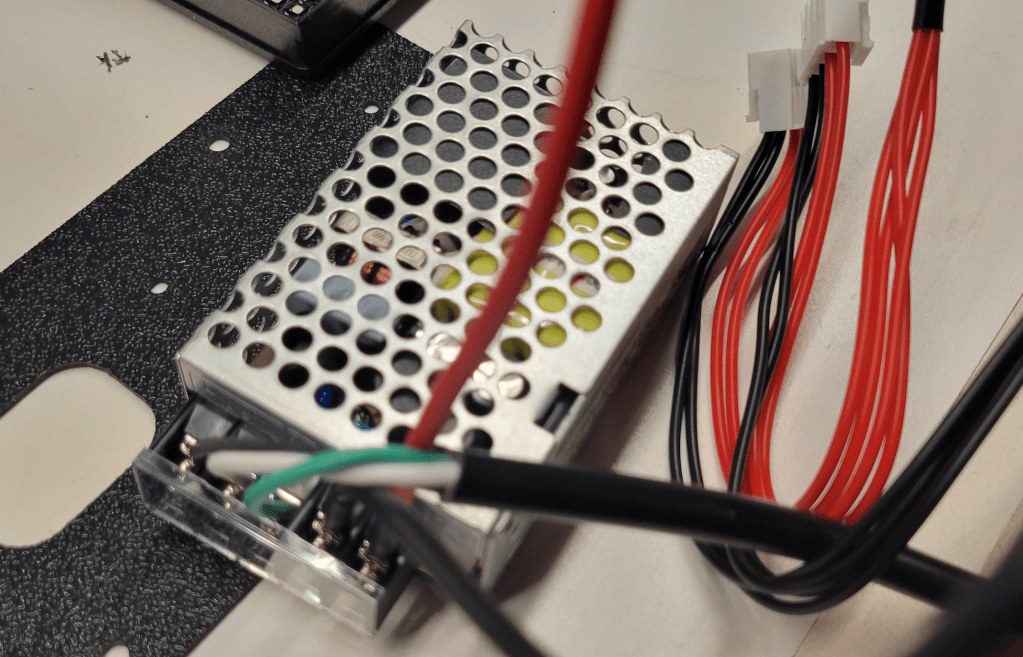
Next, attach the AC cord and the DC power splitters to the included power supply, and replace the terminal cover.
Attach the power supply to the thin black plastic mounting plate using two small screws in the kit, in the orientation shown.
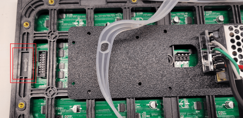
Then, in the two plate holes nearest the PSU, install the self-tapping screws to hold the plate to the panel.

Controller Board
Next, mount the Panel Panther board to the back of the panel in the orientation shown. Use the little white spacers between the board and the mounting plate.
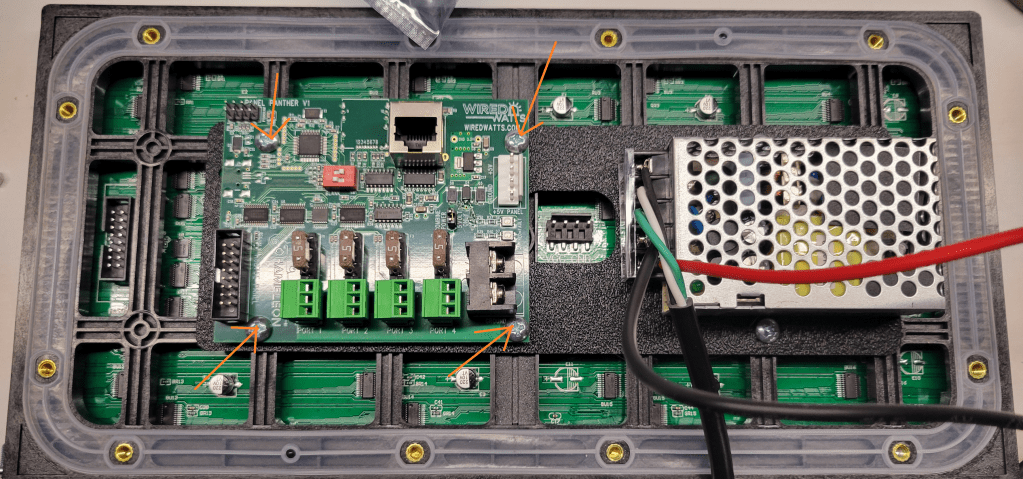
Attach the HUB panel data cable between the panel and the board. Attach the DC power connectors, one to the Panel Panther board, and the other to the P5 panel.

DIP Switches
There are two little red DIP switches on the board (see image above). Turning #2 on puts the board in test pattern mode. Turning on #1 causes the board to blank the image shortly after data signal is lost; with the switch off it will hold the image indefinitely (until more data is received, or power is lost). I have switch #1 on, and #2 off. (2025 Note: I believe that some boards are shipping with a different firmware this year and had to set #2 on. The new purpose of switch #2 is to choose panel 1 vs panel 2 in a chain of 2 panels. I did not try this, but debug function can supposedly be accessed by jumpering pins 2+4 on the header. See the WiredWatts website for updates.)
Cover
Attach the data cable from the bulkhead to the port on the board (see above).
Do you feel lucky? If you feel lucky, make sure the gasket is oriented properly (little black nubs should poke through holes in the gasket) and install the screws that hold the plastic housing to the panel. (If you do not feel lucky, maybe you should test things before you screw the cover on. 2025 Note: I assembled mine this year without testing and regretted it, the DIP switch settings have changed since 2024; testing before putting the cover on is now recommended here at merryoncherry.) This is one of the times when you should put all the screws in loosely, then tighten, probably from the center out toward the edges.
Final Assembly
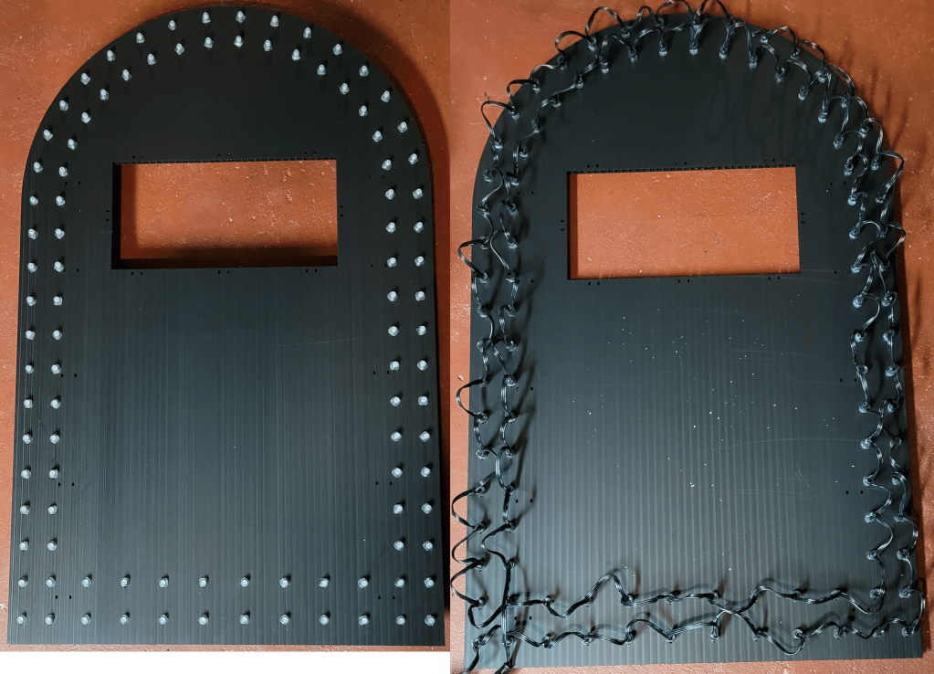
Push the border pixels into the coro, as one does. The vendor model has the pixels starting at the outside bottom left (when viewed from the back), going across the bottom, and proceeding counterclockwise around the tomb twice.
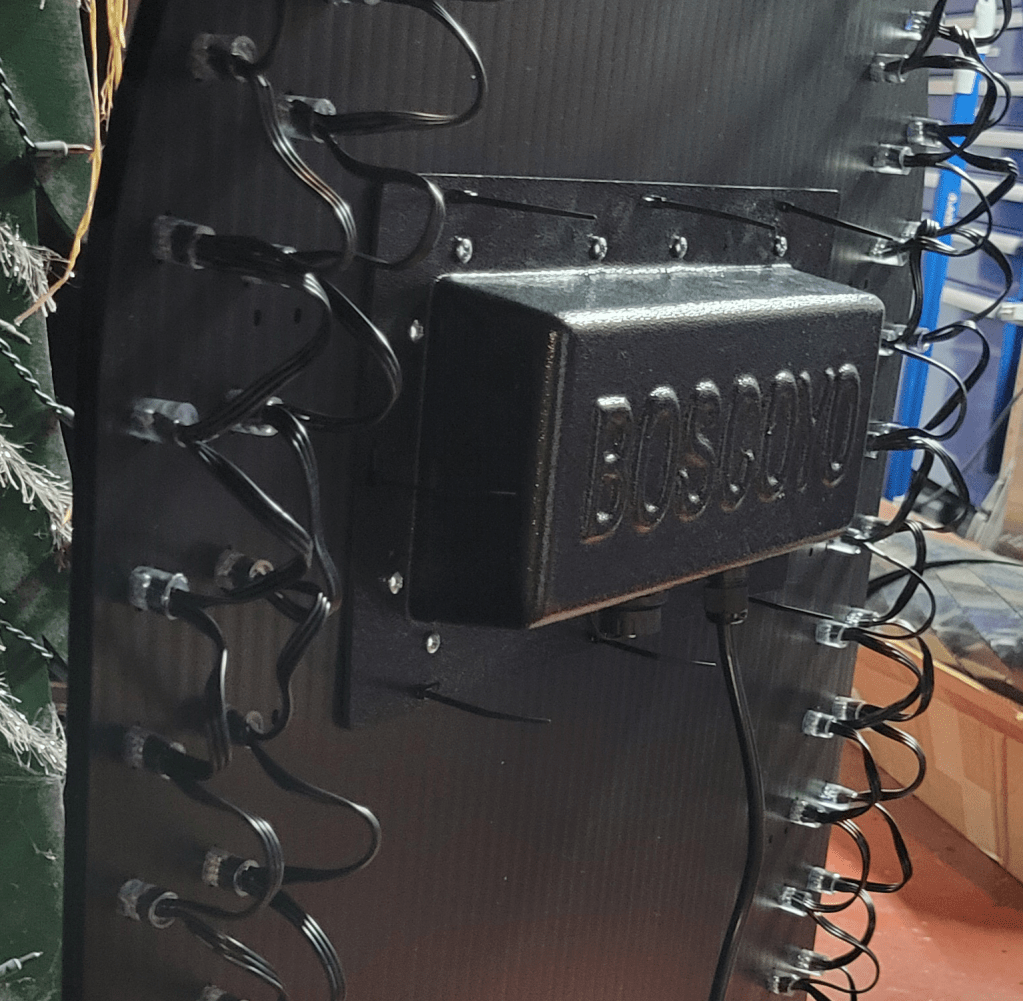
Ziptie the assembled panel matrix to the coro.
Whatever you do, do NOT trim the ends off the zip ties! Just kidding, do whatever you want, no judgment.
xLights Setup
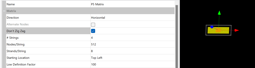
xLights setup for the matrix is reasonably straightforward, with a small wrinkle in older versions of xLights. Add a horizontal matrix with 4 strings of 512, 8 strands per string. The wiring does not “zigzag”, meaning each row starts on the left rather than going back and forth as one often does with a pixel string. This “Don’t Zig Zag” option was added in late 2023, so if you don’t have it, either upgrade to a newer xLights or use a custom model like this one for the matrix. (Or, I suppose, set the controller zigzag, if your controller offers that, but not all of them do.)
When setting a controller connection, if you see any stuff about smart receivers, make sure it is all set to dumb.
A model for the outline pixels is available in the xLights model download menu, or you can use this one which has a few more submodels defined.
Finished Tombstone
One thing I wondered about is whether the P5 panel would be brighter or dimmer than the surrounding pixels. I used 12V resistor nodes, which are known to be a bit dimmer than some of the other pixels, and thought the balance was close enough – no need to dim the panel or the pixels.
Another question I had was to the gamma setting. The panel must have some inbuilt correction; I did not need to set it to 2+ like many WS2811 pixels, but did find it to benefit from a setting of about 1.3.
Conclusion
Overall, the panel kit is well-thought-out, and easy to build. I’m quite satisfied with how these turned out. I’ve wanted to play with panels for a while now, and this was certainly a really easy way to get started. It’s also nice to have some little matrixes in the yard, adds a bit of variety, so I will definitely be putting a few of these in the show this year!
